Sections.
- GENERAL
- UTILITIES
- COMMAND FUNCTIONS
- LIBRARY ROUTINES
- INPUT/OUTPUT ROUTINES
- DISC HANDLING (DATA RECORDS)
- DISC HANDLING (SPOOLING)
- MISCELLANEOUS
TASKS
When LOS is initiated via the control panel switches, it creates core partitions for each "task" defined in the installation’s configuration table, and assigns a unique Task Number (from 1 upwards) to each I/O station and to each Printer. Each task is initiated at the start of the appropriate control program, and thereafter all tasks run asynchronously under the control of the Task Scheduler.
The I/O station Control Program outputs the
PROGRAM? prompt and, upon receipt of a valid reply, overlays the station’s core partition with the requested program and passes control to it. The program must return to the Control Program on completion (or on operator’s ESCAPE request) (by JUMP Z 1400or JUMP Z 1402), whereupon the PROGRAM? prompt will be re-output.The Printer Control Program tests the Print Queue currently assigned to the printer for the presence of work postings. If work is found, the oldest posting is removed from the queue and assigned to the printer. The appropriate program is overlaid into the printer’s core partition unless it is already in the partition, and control is passed to it.
The program must return to the Control Program upon completion (by
JUMP Z 1406). If there is no work in the queue, the Control Program waits for postings to the queue and the printer is IDLE. The operators may, by command, change the print queue assignment at any time; the Control Program will switch to the new queue as soon as it receives such instructions.INTER-TASK COMMUNICATION
I/O Station ® Printer
For any application requiring printout, the I/O station task does not directly output to a printer; rather all output is written to the disc-held Spool File for later processing by a printer task. The format and content of these intermediate Spool records is defined by the application, except that each record is 124 words long (the last 4 words of the sector are reserved for system use: double-word program name and two chain-linking words).
As a general rule, the I/O station task should create compact spool records with the minimum of processing beyond input validation; wherever possible processing and updating should be carried out (at a lower priority level) by the printer task. This improves I/O station response time, reduces the spool storage requirement and eases the problems of recovery after a cancellation request or machine fault.
An application may require several spool records to define a printout (e.g. an invoice may be of any length), but usually a single record will suffice. The first record is referred to as the header record. When spooling is complete, the spooling task posts the header record number to a pre-selected print queue, normally determined by the type of paper required, and the system adds the posting to the end of the queue.
The system inserts the station’s task number into the first word of the Spool Buffer when an I/O station starts a new program, and after each
SPOOL and each POST subroutine call (thus the receiving printer program may identify the station from which it has received work). Note: this provision does not reserve the first word of spool records.Printer ® I/O Station
The
FLASH SINGLE STATION subroutine allows any task to send a message to a specific I/O Station. A printer may identify the Station from which it has received work by the task number in the first word of the spool buffer. If this task number is stored at 3742- (within the Printer’s Task Control Area) the system will flash the station pppp PRINTED BY x when the program returns to the control program (by JUMP Z 1406).System ® Operator
The general
FLASH subroutine allows any task to send a message to all I/O Stations.Operator ® System
All I/O Stations are provided with a key which interrupts the current program and allows the operator to enter system commands. Available commands are listed in section 3 of this guide.
Operator ® Operator
Program
S is available to send a message to the screen of any or all I/O Stations.PARTITION MAP (2K VERSION)
0000-, last word is offset 3777-).Each task has its own core partition. All task partitions are of the same size and format (as defined in the Configuration Table). Because the partition maps are pre-defined and known throughout the system, there is a considerable saving in the number of parameters required by subroutines. Experience has shown a 2K partition size to be the optimum choice for Commercial applications, and all offsets quoted in this guide will refer only to a 2K partition, with a base offset of zero (i.e. first word of the partition is offset
The task OVERLAY AREA is 13 sectors long and occupies
0000- to 3177-. This will contain program code, data and work areas. Programs and Overlay Modules are loaded into the area by FETCH subroutine.The task MASTER BUFFER is one sector (128 words) long and occupies
3200- to 3377-. Used by FETCH, REWRITE and OVERWRITE subroutines as a one sector disc transfer buffer.The task SPOOL BUFFER is one sector (128 words) long and occupies
3400- to 3577-. Used by the SPOOL, UNSPOOL, POST, SPOOL & POST subroutines. A spooling task creates spool records here; an unspooling task receives spool records here (3577- contains the number of the next spool record in the chain). This buffer may be used as workspace (or as an extension to the Master Buffer) when spooling is not required.I/O STATIONS only: The task INPUT BUFFER is 128 characters long and starts at
3600-. Used by the GET and SPLIT subroutines and contains the most recent input from the station (ASCII format terminated by NUL byte).PRINTERS only: The task INNER PRINT BUFFER is 132 characters long and starts at
3600-. Used by the PRINT LINE subroutine, which always space-fills the buffer. The buffer holds one line of ASCII printout; a map of print positions against offsets is provided.The task CONTROL AREA occupies
3704- to 3777-. This is reserved for system use. The current program name (four ASCII characters) is held at 3716-.Note Task Control Programs and Outer Print Buffers are within the system core space, not part of the task partition.
PROGRAMS AND OVERLAY MODULES
02. An index to this library is also held on disc, stating the length of each module and the offset within the-task partition at which it is to be loaded.All Applications programs are held on disc as Overlay Modules. An overlay Module may be from 1 to 13 (decimal) sectors in length, and is identified by an Octal Number, range 001 to 400 (Module numbers 001 to 040 are reserved for Systems programs).
Currently, all overlay modules are contained on disc in the Overlay Module Library, assigned file identifier
A task may fetch overlay modules into its own core partition at any time (see
FETCH Overlay Module subroutine), but in practice only the most complex of applications will overrun the 13 sectors available to the initial overlay. On the contrary, it may be found convenient and practical to group several related programs into the same overlay module.Programs within LOS are identified by four character name (space filled if necessary) and type (I/O Station or Printer). A directory is held on disc giving, against each I/O station program name, the corresponding Module Number and logical Entry Point within the module. A similar directory exists for printer programs.
Overlay Modules are loaded and amended by the utility program
OP. A systems utility program (PLM) is available to allocate disc space to a new overlay module, and to maintain the library index and program directories.When an overlay module is fetched into core by program name, an option of the system may automatically resolve a block of offset addresses placed at the beginning of the module. (The library index contains flags indicating the modules to which the option applies.)
INPUT/OUTPUT
Direct Access
All tasks may transfer data to and from disc held files. Programs refer to files by a two-digit octal number, the File Identifier. Identifiers 00 to 10 are reserved for Systems Files, 11 to 77 for Applications Files.
The association between File Identifier and Data-Set on disc is, in principle, flexible. But as yet LOS does not provide file opening and closing facilities; therefore all files should be regarded as pre-opened by the system. This should be adequate where the machine is dedicated to the application.
Records within a Direct Access data set are identified by their relative record number; the first record number one. Records may be buffered several per sector (128 words), but records exceeding one sector cannot be contained within the task’s Master Buffer, which is the implied transfer buffer for the
FETCH, REWRITE and OVERWRITE subroutines. The system provides automatic de-buffering and re-buffering facilities.Disc Updates
The possibility of a simultaneous update of the same record (or, more precisely, the same sector) by two different tasks is eliminated within LOS because no mechanism is provided to write a record to disc without having first read that record and locked the entire disc transfer system. The lock must still be in force when the record is rewritten or overwritten.
Where it is necessary to prevent updating an entire file for a period of time this must be recognised and dealt with by the programs concerned.
THE BOOTSTRAP
MANUAL.To initiate LOS proceed as follows.
1. Place any exchangeable disc (MASTER or SECURITY) holding a copy of the Operating System and holding the configuration Table appropriate to the installation onto Device 70 Drive 0.
2. Insert key, turn to
3. Press
RESET. Wait for +15 volt light to come on.4. Load the five-word bootstrap at
000100:004400
010670
010570
011470
020104
Note: This bootstrap is permanently core resident whilst LOS is running.
5. Load MA and PC with
0001006. CLEAR THE SWITCHES.
7. When the disc is READY, press
CONTINUE. Turn key to NORMAL and remove.Initiation takes approximately one second. Provided the disc holding the System Control Record and the disc holding the program library are on-line, all I/O stations will bleep and display
PROGRAM?; otherwise all I/O stations will flash a message indicating which disc is required.RECOVERY FROM SECURITY
CONTINUE and remove the key. Initiation will occur and copying proceeds automatically. The I/O stations will flash any requests for discs not on line. When copying is complete, all I/O stations will bleep and display PROGRAM?The above Bootstrap procedure should be carried out up to step 6 inclusive. The appropriate SECURITY disc must be placed on DEVICE 70 DRIVE 0; in the case of recovery of both FIXED and EXCHANGEABLE MASTER Discs this is the EXCHANGEABLE MASTER’s Security Disc.
After clearing the switches at step 6, raise switches 9 and 10. When the disc is READY, press
ADDITIONAL FACILITIES OF THE BOOTSTRAP
The control panel switch register acts as a function indicator to the initiator:
|
ALL SWITCHES CLEAR |
Normal Start-up. |
|
SWITCH 9 UP |
Recovery from Security required. |
|
SWITCH 10 UP |
Initialize Device 70 Drive 0 Fixed Disc. |
|
SWITCH 11 UP |
Initialize Device 71 Drive 0 Fixed Disc. |
|
SWITCH 12 UP |
Initialize Device 72 Drive 0 Fixed Disc. |
|
SWITCH 13 UP |
Initialize Device 73 Drive 0 Fixed Disc. |
|
Note: Switches 10-13 operate only in conjunction with switch 9 and only if all other switches are down. "Initialize" means label the disc as number 300 octal (i.e. system scratch disc). |
|
|
SWITCH 7 UP |
Intercept required. The OS will be read into core; control then passes to the Systems Programming OP utility to enable Operating System and/or Configuration Table amendment. |
|
SWITCH 17 UP |
Intercept required. As for switch 7, except that switches 16-9 indicate the INPUT Device Code, 8-1 indicate the OUTPUT Device Code for the Systems Programming OP utility. |
|
SWITCH 16 UP |
Intercept for MK1 PACKAGE Amendments. The OS is read into Core and Control passes to the Systems Programming OP utility in such a manner as to use the utility to amend MK1 PACKAGE programs. |
|
SWITCH 6 UP |
Re-configure to single task. This facility is provided to overcome start-up problems caused when the physical configuration does not correspond to the configuration table held on the source disc (in particular, if there is insufficient core to match the requirements of the table, a parity halt ( 003356) will occur).The facility amends the configuration table on UNIT 70 exchangeable cartridge to one I/O station and no printers (the single task is assigned core partition 5/0000). Initiation then proceeds as indicated by switches 17-7.The I/O station is assumed to be an AlphaNumeric Keyboard. If it is a 16-line VDU, raise switch 1. If it is a 24-line VDU, raise switch 2. When the PROGRAM? prompt is obtained, program ACT may be entered to amend the configuration table to the full physical configuration. |
SYSTEM HALTS
HALT subroutine) for the reasons given below.The system may halt a task (by calling the
|
|
|
|
|
or OVERWRITE called out of context. "A" register contains program back address. |
|
File Type not supported. "A" register contains program back address(Check that the File Identifier refers to a Direct Access File). |
|
|
|
|
|
SPOOL back address. The-program must be corrected to assign a non-zero print queue to the task before calling SPOOL, by means of the SPECIFY I/O STATION PRINT QUEUE subroutine. |
|
HALT message) is not entered in the Print Program Directory. |
|
WRITE to Protected Sector. |
LOS DISC LAYOUT
|
|
|
|
|
|
|
|
|
|
|
|
|
|
000000) |
|
|
|
|
|
|
|
|
|
|
|
|
|
|
|
|
|
|
CONFIGURATION TABLE
Purpose: To remove from the operating system, as far as practicable, installation and hardware dependent parameters. Thus the bootstrap will load the "raw" OS into core, then the initiator will read the 3 sector Configuration Table into
0/0400 and, by reference to the information in the table, convert the OS into a working version. The Configuration Table is then overlaid by the permanently core resident System Control Record.Notes:
- The initiator copies
AMENDMENT OF CONFIGURATION TABLE
- Amend the table as required, and escape back to
COPY; at NO OF SECTORS prompt, enter CT). DO NOT FORGET to carry out this step (otherwise security copies of the Fixed Cartridge will not hold the correct configuration table).WARNING The above amendment sequence updates the table held on the EXCHANGEABLE cartridge, Device 70, Drive 0 only. Where the fixed cartridge acts as a Master Disc, the amended configuration table must be copied to the Fixed cartridge (by restarting system and using program
Note: This warning also applies to amendments to the Operating System. To copy the OS, at
NO OF SECTORS prompt, enter OS.OFFSET ADDRESSING
The Molecular hardware implementation allows a program to run in any page of core (1K words beginning on a 1K boundary) provided it does not require indirect addressing (i.e. does not need to refer to locations outside that page or Zero page).
Indirect addresses must, however, be absolute addresses. Therefore, if a program requiring indirect addressing is to be run in any page without modification:
| Many (but not necessarily all) of its indirect addresses must be specified as offsets from a specified base point (normally the start of the first page of the program). | |
| These offsets must be resolved to absolute by software before access by Memory Reference Instructions. |
LOS assigns each task a fixed 2K-core partition for its exclusive use. When programming it is convenient to specify addresses within the 2K partition as offsets from the beginning of the partition, address references outside the partition being specified as absolute.
An offset address is indicated on coding sheets by a "
-" suffix (range 0000- to 3777-), and in core by Bit 17 set (range 200000 to 203777)All the applications subroutines within LOS allow address parameters to be specified as Offset from the Partition Base or as Absolute, according as bit 17 of the parameter is or is not set, respectively. The
RESOLVE OFFSET, RESOLVE OFFSET BLOCK, LOAD A FROM OFFSET, STORE A AT OFFSET subroutines are available to handle offset addresses within user programs. If offset pointers are blocked at the beginning of an Overlay Module an option of the system may resolve the block automatically when the Overlay is fetched from disc by program name (16 words reserved for this purpose should be ample).BYTE ADDRESSING
Convert Binary to ASCII subroutine call by 11 characters each time, and is best achieved as follows:1 Byte = 8 bits. A Molecular 17-bit word may hold 2 bytes; bits 16-9 are referred to as the Top byte, bits 8-1 as the Bottom byte.
ASCII characters are always held in bytes, one character per byte. Only 7 bits are required to define an ASCII character; the top bit of the byte is not used and therefore always zero in core. Bit 17 of a word containing ASCII is redundant and therefore always zero.
When passing character string addresses to subroutines, the parameter must indicate whether the string begins in the top or bottom byte. The convention is to set bit 16 of the parameter if the string starts in the bottom byte.
Notes
1. Byte addressing imposes a 32K-word addressing limit on the string addressed. This may be overcome (subject to modification of LOS) provided all byte addresses over 32K words are specified as offsets.
- When processing character strings, it is expedient to convert the byte address to an "absolute byte number".
Example: To set up a certain print line comprising several 11 character numeric fields, it is desired to program a Binary to ASCII conversion loop. This loop involves incrementing P3 of the
LDA P3 of call
LRA
ADA Z 0213 CF11
RRA
STA P3 of call
CORE MAP
5/0000 and 10/0000).Minimum core requirement for LOS is 12K words; this includes two 2K task partitions (at
Absolute Zero Page is directly addressable from all tasks and therefore contains common data and pointers, as mapped in the System Reference.
|
From |
To |
|
|
0/0400 |
0/1177 |
System Control Record |
|
1/0000 |
2/1777 |
Library Routines, Command Handler. |
|
3/0000 |
3/0577 |
Available for Systems Programming use. |
|
3/0600 |
4/1777 |
Library Routines, Service Routines. |
|
5/0000 |
6/1777 |
Task Partition 1 |
|
7/0000 |
7/1777 |
System list area and data area. |
|
10/0000 |
11/1777 |
Task Partition 2. Note: The address and instruction decode routines (used by OP and LIST utilities) reside in 10/0000 to 10/1377. Where programming work is to be carried out, it is preferable to avoid using this task partition if possible. |
|
12/0000 |
13/1777 |
Disc Transfer and handling and Task scheduler. |
|
14/0000 |
37/1777 |
Task Partitions and/or shared Buffer Areas. |
|
40/0000 |
77/1777 |
Shared Buffer Areas, systems workspace. |
ACT (Amend Configuration Table)
|
Step |
Prompt |
Action |
|
|
1 |
PASSWORD |
Enter Systems Password. |
|
|
2 |
DISC NO |
Either enter System Dic Number (range 001 to 377 octal),or ESCAPE to PROGRAM? |
|
|
3 |
The Configuration Table held at Sector 000042 on the stated disc is read into core. Amendments made to the table by the following instructions have no effect on the existing configuration until the system is re-bootstrapped off the relevant disc. |
||
|
4 |
AMEND DEVICE TYPES? |
Either ACCEPT to go to step 5,or REJECT to go to step 8. |
|
|
5 |
TASK n IS xxxx? |
where n is the six-digit octal Task Number and xxxx is the four-character device identifier currently allocated to the task. Either ACCEPT to leave the device type unchanged, or enter new device identifier (see below), or enter F if Task n does not exist (end of list – program goes to step 7).Valid device identifiers are: |
|
|
ANK |
Alpha-Numeric Keyboard (8 or 16 character display). |
||
|
V16 |
16-line VDU (also valid for 8-line VDU). |
||
|
V24 |
24-line VDU. |
||
|
DRI |
DRI Printer. |
||
|
C400 |
CDC 400 lpm Printer. |
||
|
BCL |
BCL Serial Printer. |
||
|
CENT |
Centronics Printer. |
||
|
EMU |
VDU as emulator for a printer. |
||
|
All required I/O Stations must be entered before Printers. The first VDU input is assigned device codes 50/40, the next 51/41, etc. Where both 16- and 24-line VDUs are present, the order of input will be determined by their device codes. |
|||
|
6 |
Program returns to step 5 for the next task, until code F is encountered. |
||
|
7 |
The amended table is written back to disc. |
||
|
8 |
AMEND TASK DATA? |
Either ACCEPT to go to step 9,or REJECT to skip to step 13. |
|
|
9 |
TASK n BASE pp/ccss? |
Either ACCEPT to leave core partition unchanged,or enter new Absolute Address of task’s Core Partition. |
|
|
10 |
If task is an I/O Station: COMMANDS PRINTER x? |
Either ACCEPT to leave command printer unchanged, or enter Printer Code (one character A, B, ...)or enter N if station is not allowed to command a printer.Note: at a one printer installation, the printer code should always be A. |
|
|
If task is a Printer: START QUEUE n? |
Either ACCEPT to leave start-up queue number unchanged, or enter new start-up queue number (range 0 to max queue number).Note: this is the queue the printer will go to whenever the system is re-bootstrapped. |
||
|
11 |
Program returns to step 9 for the next task, until the last task has been processed. |
||
|
12 |
The amended table is written back to disc. |
||
|
13 |
AMEND PASSWORDS? |
Either ACCEPT to go to step 14,or REJECT to go to step 17. |
|
|
14 |
PASSWORD n? |
Either ACCEPT to leave Password n unchanged,or enter new password (max nine characters). Note: the new password does not appear on the screen. |
|
|
15 |
Program goes to step 14 for the next password, until all four passwords have beedn processed. |
||
|
16 |
The amended table is written back to disc. |
||
|
17 |
START FILE TABLE n? |
Either ACCEPT to leave start-up file table unchanged,or enter new start-up file table number (range 0-3). |
|
BOOT (Bootstrap Utility)
|
Step |
Prompt |
Action |
|
|
1 |
PASSWORD |
Enter Password 1. |
|
|
2 |
MASK |
Either enter LOS Switch Register Mask: |
|
|
0 |
Restart |
||
|
400 |
Recover from Security |
||
|
1400 |
Recover from Security after scratching Unit 70 Fixed Disc |
||
|
3400 |
Recover from Security Security after scratching Unit 70 and Unit 71 Fixed Disc |
||
|
or enter MKI "TCRD" Address (0 = Standard (8K) Package "HOST"),or ESCAPE to PROGRAM? |
|||
|
3 |
SOURCE DISC |
Either enter LOS Source Disc Number,or enter 5 if MK1 system is to be Bootstrapped,or ESCAPE to PROGRAM?. |
|
|
CAUTION: the Source Disc must be loaded onto Unit 70. |
|||
|
4 |
The bootstrap procedure will be carried out when the Source Disc is on-line. |
||
CALC (Octal Calculator)
|
Step |
Prompt |
Action |
|
1 |
Station displays column headings ---OCTAL--- DECIMAL |
|
|
2 |
The calculator’s accumulator is cleared. |
|
|
3 |
+DECIMAL |
Either enter Decimal Integer (+ or -),or ESCAPE to go to step 1 to clear the accumulator (returns to PROGRAM? if the accumulator is already clear). |
|
4 |
Program displays, on the same line, the double-word octal equivalent of the Integer input. |
|
|
5 |
The integer input is added to the accumulator and the value of the accumulator is displayed, on the next line, in double-word octal and in Decimal. |
|
|
6 |
Program goes to step 3. |
CDL (Check Digit List)
Produces a printout of numbers with their associated check "digits".
|
Step |
Prompt |
Action |
|
1 |
Station displays PRINT Q n where n is a Plain Paper Queue. |
|
|
2 |
FIRST NO |
Either enter Number at which the print-out is to start,or ESCAPE to PROGRAM?. |
|
3 |
LAST NO |
Enter Number at which printout is to end. |
|
4 |
Program posts the printout to the indicated Print Queue and goes to step 2 for the next range. |
COPY (Copy Discs Utility)
This utility will copy any number of sectors from any part of one disc onto any part of another or the same disc (unless the receiving sectors are "protected")
The target area is re-read and a software "hash-check" is carried out.
If the source and target areas overlap, it should be noted that the copying is carried out 8 sectors at a time, using a 1K-core buffer.
|
Step |
Prompt |
Action |
|
1 |
PASSWORD |
Enter Systems Password. |
|
2 |
SECTORS (DECIMAL) |
Either enter the number of sectors to be copied,or ACCEPT, if same number of sectors as last time (preset 12992 on entry),or enter P if target area is protected (Protection Override) (program returns to step 2),or enter OS to copy Operating System (program omits steps 4 and 6),or enter CT to copy Configuration Table (program omits steps 4 and 6). |
|
3 |
SOURCE DISC |
Enter Source disc number in Octal. |
|
4 |
START SECTOR (OCTAL) |
Enter first sector of source disc to be copied. |
|
5 |
TARGET DISC |
Enter Target disc number in Octal. |
|
6 |
START SECTOR (OCTAL) |
Enter first sector of target disc to receive copy. |
|
7 |
PROCESS? |
Either ACCEPT to go to step 8,or REJECT to return to step 2. |
|
8 |
Station will BEEP on completion of the copy, and go to step 2. |
DLU (Disc Labelling Utility)
|
Step |
Prompt |
Action |
|
1 |
PASSWORD |
Enter Systems Password. |
|
2 |
DEVICE 000070? |
Either ACCEPT if indicated device holds the disc to be labelled,or enter Device Identifier (see below), or ESCAPE to PROGRAM? |
|
3 |
DISC N0 |
Either enter Disc No in Octal (range 001 to 377),or ESCAPE to step 2. |
|
4 |
SECURITY? |
Either ACCEPT if this is a Security Disc,or REJECT if this is a Master Disc. |
|
5 |
Program will label the disc on the indicated device and go to step 3. A Security Disc will be marked "All sectors protected", a Master Disc will be marked protected up to sector 000206 octal inclusive. |
 Note.
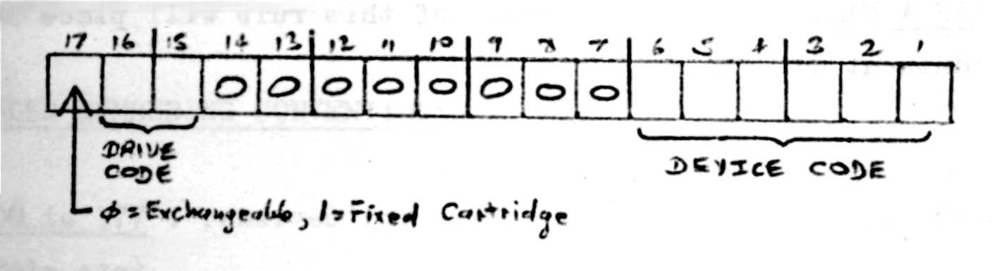
The Device Identifier is a 6 digit Octal Number in the format:
Note.
The Device Identifier is a 6 digit Octal Number in the format:
CAUTIONS
DISC LABELS
0 to 377.Each disc is identified to the operating system by Disc Number. For programming convenience the number is always given -in Octal, range
The disc number is held in the first word of sector
40 (octal) of the disc, and this sector is therefore called the Disc Label. The second word of the label contains the number of the first "unprotected" sector on the disc (protection is a software feature designed to intercept any inadvertent write onto "read only" areas of the disc: LOS provides only are such area per disc).RECOMMENDED NUMBERING CONVENTIONS
|
|
|
to 007 |
408, a MK I package disc will acquire disc number 005 (with all sectors protected). |
|
to 277 |
|
|
|
|
|
|
|
|
|
|
|
|
|
|
|
|
|
to 377 |
|
|
Information provided by Joe Templeman